Geophysical well-logging methods are used to obtain geological information about well sections, detect and assess mineral deposits, monitor deposit development, and examine the technical condition of wells. These methods allow for the study of the physical properties of rocks under borehole conditions.
Geophysical well-logging methods include electrical, radioactive, acoustic, magnetic, thermal, and other types of investigations. They allow the construction of borehole cross-sections as a complex of physical characteristics, such as specific electrical resistivity, radioactivity, thermal conductivity, acoustic wave velocity, and other parameters.
These methods are also used to monitor the technical condition of wells and to investigate active wells during deposit development. Therefore, the quality and completeness of the data must be at a high level. For this reason, LTS specialists utilize tools from leading companies in the USA, Australia, Canada, and Sweden.
Electrical and Electromagnetic Methods of Well Logging
Electrical and magnetic methods of borehole logging include variations based on the study of natural and artificial electromagnetic fields in rock formations.
Natural electromagnetic fields in the Earth’s crust arise due to electrochemical processes, magnetotelluric currents, and other geophysical phenomena.
Artificial electromagnetic fields are created in rocks by generators using direct or alternating current of various intensities. These are man-made tools used for investigating the structure of the Earth’s crust, and for locating, exploring, and developing mineral deposits.
The classification of electrical logging methods is based on the origin of the electromagnetic field under study and its temporal behavior—i.e., frequency.
By origin, methods are divided into two main groups:
- Those based on natural electromagnetic fields
- Those based on artificial fields
By frequency, methods are grouped as:
- Direct current (DC) methods
- Quasi-static (low-frequency) methods
- Alternating current (AC) methods, further divided into low-frequency and high-frequency categories.
The following specific methods are used:
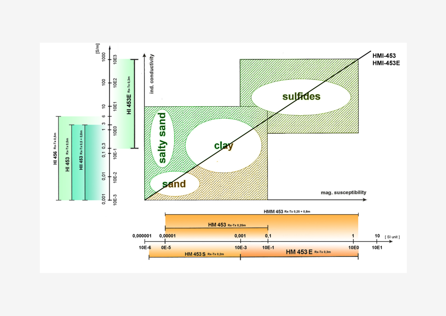
Induction logging (IL), dielectric logging (DL), and radiowave methods for artificial AC fields
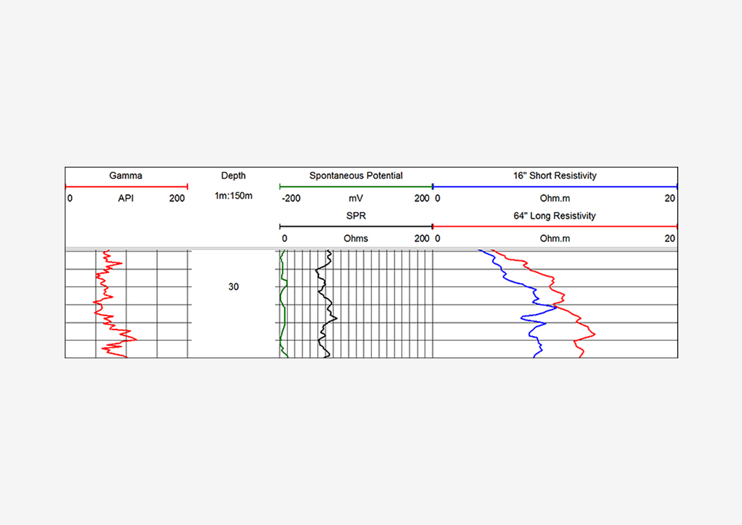
Self-potential (SP) for studying natural electrical fields
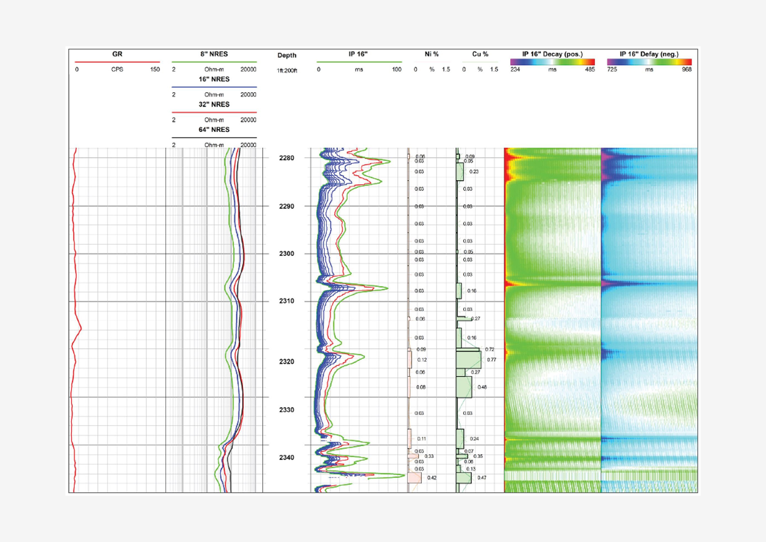
Apparent resistivity (AR), micro-logging (ML), grounding resistance (GR), current logging (CL), and induced polarization (IP) for artificial DC and quasi-static fields
Acoustic Logging
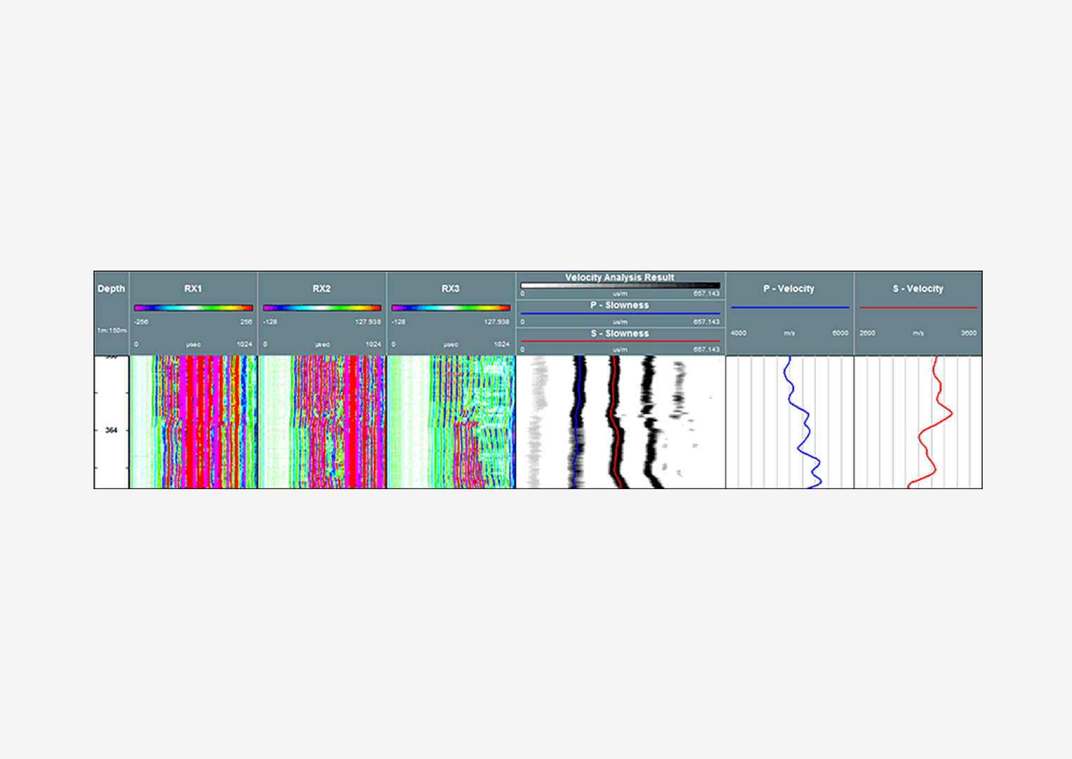
Acoustic logging is based on the study of elastic wave characteristics in the ultrasonic and sonic frequency ranges within rock formations. During acoustic logging, elastic vibrations are generated within the well and propagate through both the well and the surrounding rock. These vibrations are detected by receivers placed within the same borehole.
In their natural state, rocks behave almost like elastic bodies. When an external force briefly acts on an elastic medium, it causes stress that leads to particle displacement. This results in two types of deformation:
- Volumetric deformation (compression or expansion)
- Shear deformation (distortion of shape)
The sequential propagation of such deformation through the medium is referred to as an elastic seismic wave, which travels outward in all directions. The wavefront is the boundary between the region where particle motion has begun and the untouched region.
Lines perpendicular to the wavefront are called rays. In a homogeneous medium, rays are straight; in a heterogeneous medium, they curve.
Wavefront propagation is described by the Huygens–Fresnel principle, where each point on a wavefront acts as a source of secondary wavelets, and rays represent the direction of energy transfer.
Two main wave types are identified:
- P-waves (longitudinal): cause only volumetric deformation, with particles oscillating in the direction of wave propagation.
- S-waves (transverse): involve shape deformation, where layers slide past one another. Particle motion is perpendicular to wave propagation. S-waves occur only in solid materials.
When an elastic wave encounters a boundary between two media with differing elastic properties, part of the energy reflects (forming a reflected wave), and part continues through (as a refracted wave). The refracted wave changes direction depending on the difference in acoustic impedance (product of density and velocity) between the media.
There are two main forms of acoustic logging:
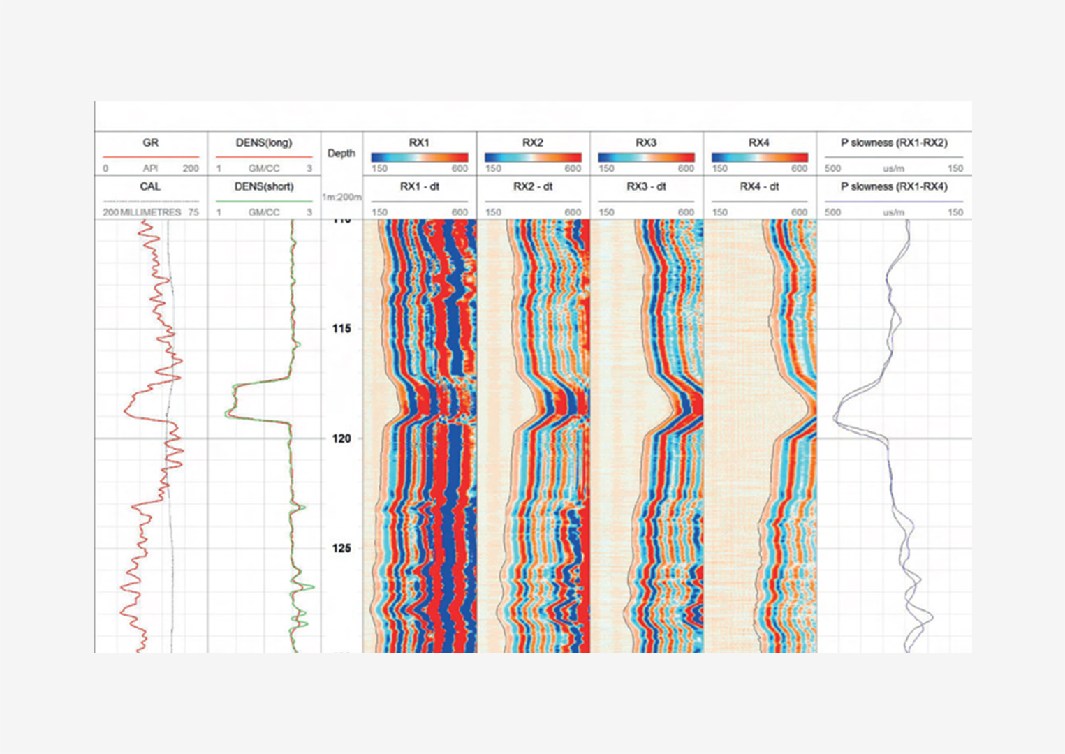
- Velocity logging (∆t logging): determines the velocity of elastic waves through rocks by measuring the interval transit time ∆t = (t₂ – t₁)/S (μs/m).
- Attenuation logging: measures how wave amplitude decreases as it travels through the rock. This attenuation depends on factors like emitter strength, distance from source to receiver, and rock properties.
Elastic wave velocity is influenced by mineral composition, porosity, and pore shape, and thus correlates with lithological and petrographic properties.
Attenuation properties vary more significantly than velocities and are particularly sensitive to geological conditions. Notably, gas-bearing, fractured, and cavernous rocks show strong attenuation. Clay content also significantly affects wave damping.
Acoustic logging measures the wave velocity over the base interval of the probe. Rocks beyond this interval do not affect readings. For interpretation, velocity curves are plotted for individual beds of varying thicknesses within a homogeneous host rock, typically using a three-sensor probe with the reading point centered in its base.
Flowmeter Logging
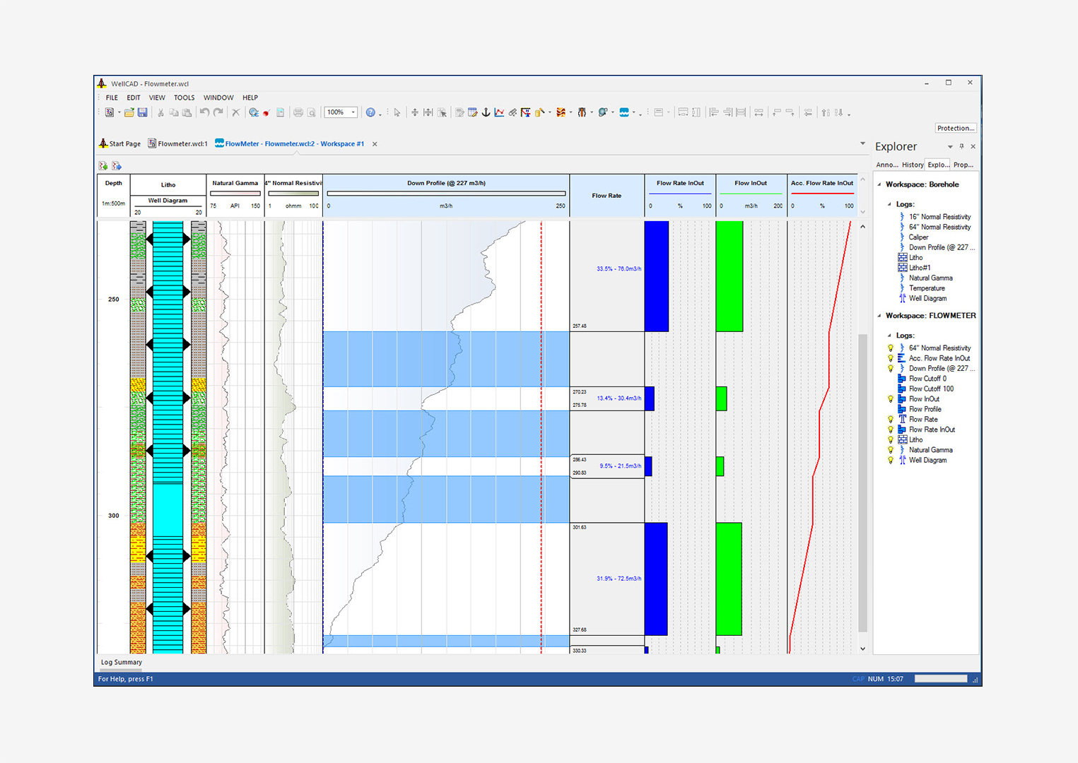
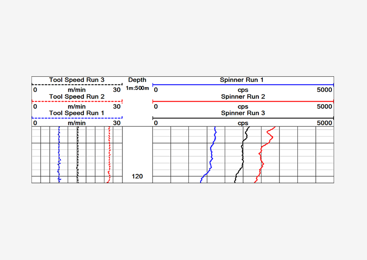
Flowmeter logging is one of the primary methods for studying the dynamics of fluid intake and withdrawal in production and injection wells. It involves measuring the velocity of fluid movement within the borehole using specialized instruments called flowmeters.
Flowmeter logging is used to solve the following tasks:
- In operating wells: to identify the intervals of fluid inflow or absorption
- In shut-in wells: to detect fluid crossflow between perforated zones
- To measure total production (discharge) or flow rates from individual formations separated by non-perforated intervals
- To construct inflow or injectivity profiles for specific reservoir intervals or for the entire reservoir
Types of flowmeters:
- Mechanical flowmeters
- Thermo-inductive (thermal) flowmeters
Based on the logging setup, flowmeters are categorized into:
- Packers and packerless systems
- Autonomous (internal signal recording) and telemetric (signals transmitted to surface via cable) flowmeters
Typically, a mechanical flowmeter is lowered to the top of the uppermost perforated interval. The resulting curve shows the quantity of fluid passing through the borehole cross-section at various depths and is called an integral flowmeter log. This log represents the cumulative flow of all zones located below the measurement point. In zones of inflow, the readings increase; in zones of absorption, the readings decrease.
From the integral log, a differential inflow/absorption profile can be constructed, showing the intensity of flow per unit thickness of the formation.
Thermoelectric flowmeters operate based on the relationship between the cooling rate of a heated resistance element placed in the fluid flow and the average linear flow velocity.
Caliper Logging
Caliper logging measures the actual diameter of a borehole, which often deviates from its nominal diameter—the diameter of the drill bit used. An increase in borehole diameter (cavern formation) commonly occurs in zones of clay or clay-rich formations (e.g., marls) due to:
- Hydration of fine-grained clay particles
- Erosion caused by high-pressure fluid jets from bit nozzles
Using saline drilling fluids reduces clay hydration, thereby slowing cavern formation.
Diameter increases are also observed in salt and gypsum formations due to their dissolution in drilling fluid.
In fractured formations, borehole enlargement may also occur due to mechanical weakening during drilling. Nominal diameters are typically preserved in hard, competent rocks such as limestones, dolomites, and dense sandstones.
Reduction in borehole diameter may result from clay particle deposition against permeable layers due to drilling fluid filtration. This creates a mud cake on the borehole wall, reducing its diameter. The mud cake can be several millimeters to over 5 cm thick.
Knowing the actual borehole diameter is essential for:
- Calculating annular volume during casing cementing
- Selecting locations for casing shoes, filters, packers, and formation testers
- Monitoring borehole integrity during drilling
Caliper log data is also used in interpreting geophysical logs, identifying lithological boundaries, and assessing rock types.
Measurement tools:
Caliper profilers, which measure diameters in two perpendicular planes and report the average or semi-sum of these values
Calipers with mechanical arms that convert movement into electrical signals, sent to the logging station and recorded as a caliper log
Inclinometry
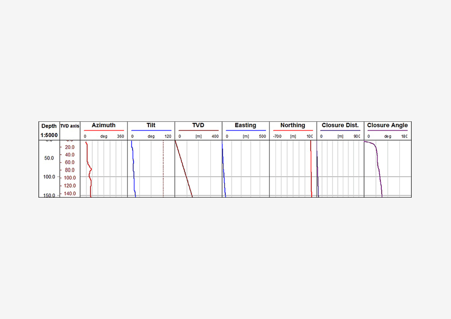
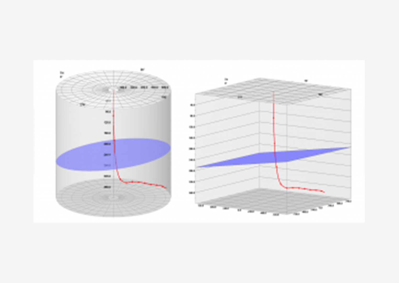
Boreholes are designed as either vertical or directionally inclined, depending on geological, geomorphological, and technical conditions. During drilling, the borehole path often deviates from the planned trajectory due to geological and mechanical influences, resulting in borehole curvature.
At any depth interval, the borehole’s spatial position is characterized by:
- Inclination angle (δ) — the deviation from vertical
- Azimuth (φ) — the compass direction of the deviation
The plane that intersects both the vertical line and the borehole axis at a given depth is known as the curvature plane.
Inclinometry provides critical data for:
- Determining the true spatial location of the borehole bottom
- Constructing geological cross-sections, structural maps, and other subsurface models
Deviation measurements are performed using inclinometers, which detect and record changes in borehole angle and direction throughout its depth.
Sample Collection
Sample collection is intended for retrieving downhole fluid samples into hermetically sealed, transportable containers for subsequent laboratory analysis, as well as for collecting water samples from hydrogeological wells. Each trip in the well typically retrieves one depth-specific sample.
Sampling methods include:
- Piston method (vacuum type sampler): The sampler is held static in the well. A piston mechanism draws fluid into a sealed container, preventing degassing and preserving the original sample composition.
- Flow-through method: The sampler’s internal chamber is exposed to the borehole fluid while descending. Once the target depth is reached, upper and lower inlet valves close, sealing the sample inside.
Sampler delivery and control methods:
- Cable-deployed with surface control:Powered and controlled via standard logging cables and surface equipment; suitable for managed operation at specific depths.
- Wireline, coiled tubing, or tubing-deployed (autonomous): These use battery-powered programmable samplers, which are pre-configured to collect samples at a defined depth and time, without real-time control from the surface.
Video Logging
Video logging is an integral part of geophysical surveys and is often conducted alongside drilling and maintenance operations in exploration and production wells. It is especially effective for monitoring and diagnosing the technical condition of a well, including during emergency and fishing operations.
Using axial and radial cameras, the system enables detailed observation of mechanical damage in the wellbore, such as:
- Breaks and ruptures
- Corrosion holes and leaks
- Misalignments and deformation of casing strings
- Foreign objects in the well
- Collapse or blockage in the open hole section
The video allows accurate determination of:
- Depth, shape, and dimensions of the observed objects
- Water movement, including direction, character, and velocity within the well
Based on these results, it is possible to:
- Assess the integrity of the casing shoe
- Identify zones of active water inflow or absorption
- Detect crossflow between aquifers
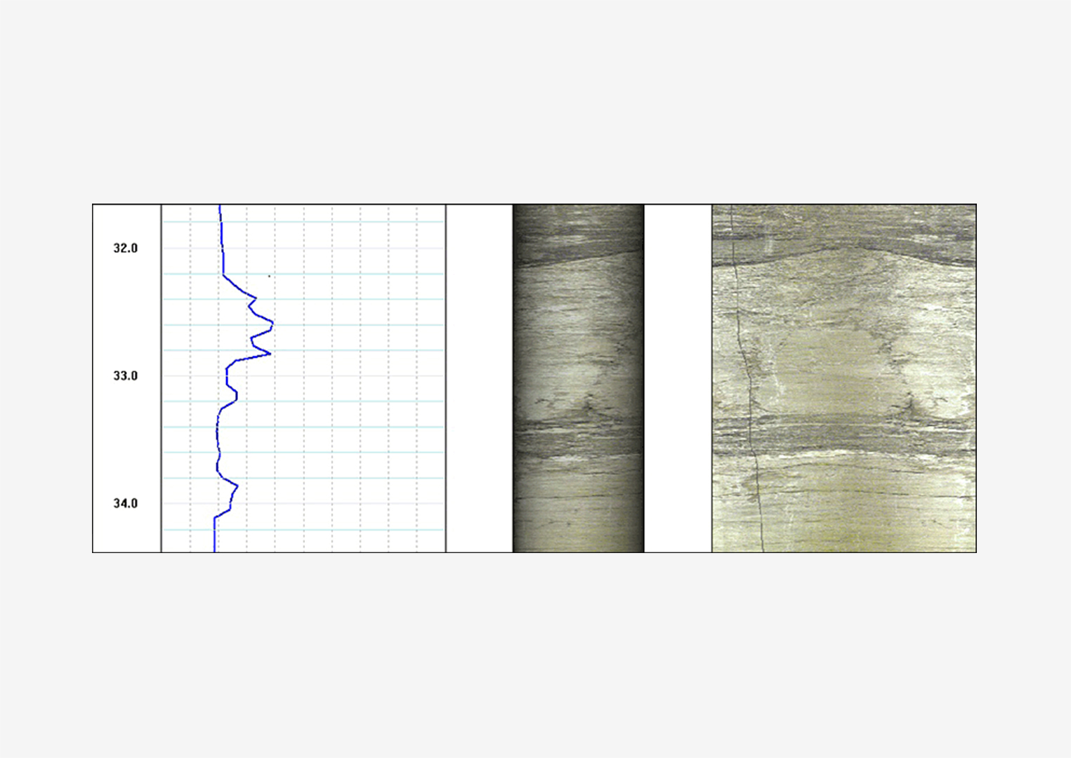
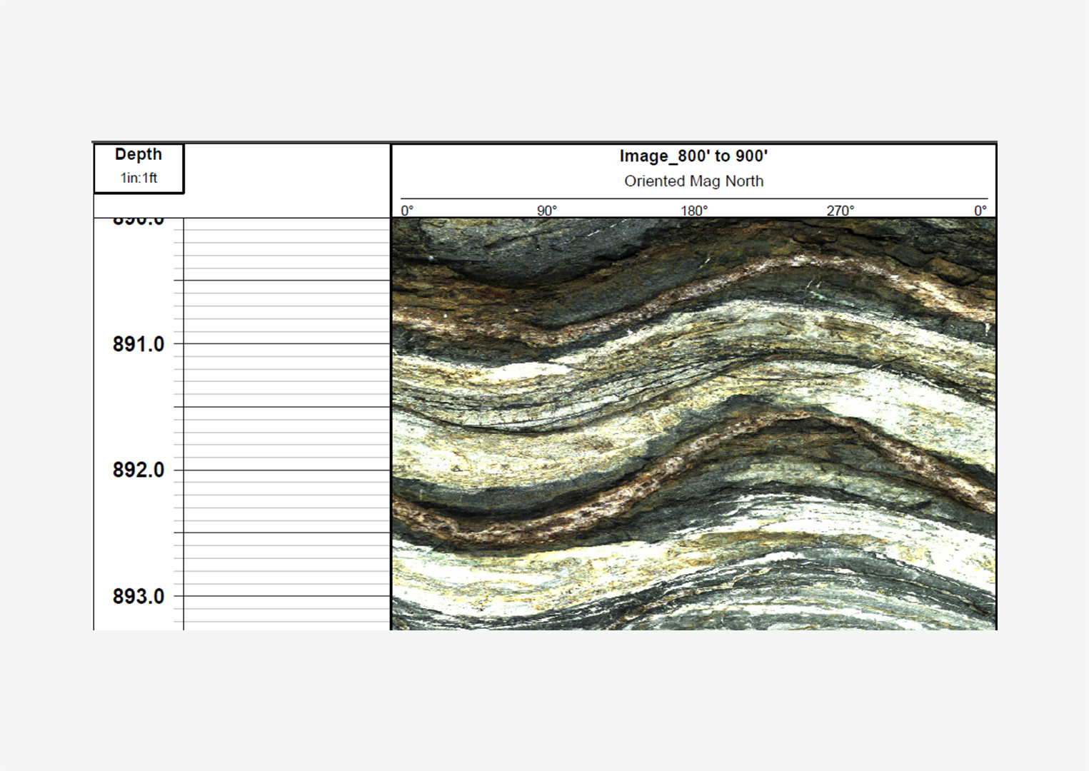
The system generates high-resolution digital images of the borehole wall with 360° continuous coverage, regardless of whether the environment is air-filled or water-filled. Resolution can reach up to 1800 pixels around the well circumference, making it ideal for:
- Lithological, mineralogical, and structural analysis
An integrated orientation module consisting of a 3-axis fluxgate magnetometer and accelerometers allows:
- Global coordinate referencing
- Determination of borehole azimuth and inclination
Applications include:
- Inspection of casing conditions
- Oriented structural mapping of borehole walls
- Detection and evaluation of fractures
- Identification of thin beds
- Measurement of bedding dip
- Lithological and mineralogical characterization
Resistivity Logging
Resistivity logging involves measuring the specific electrical resistivity (ρₛ) of the borehole fluid using a downhole resistivity probe. These resistivity values are essential for calculating the true formation resistivity from apparent resistivity data.
Measurements are also used to locate zones of water inflow, since changes in fluid salinity affect its resistivity. Because ρₛ is highly temperature-dependent, resistivity logging is typically paired with temperature measurements for accurate interpretation.
The downhole resistivity probe is a compact logging tool with an electrode spacing of approximately 2–3 cm. In its simplest form, the tool is housed in an insulating tube with open ends. Inside, three ring electrodes (labeled A, M, and N) form a single-gradient resistivity array.
As the probe moves through the borehole, fluid flows freely through the tube. The tube acts as an electrical shield, isolating measurements from the casing, borehole wall, or external formations. Resistivity logging is conducted similarly to conventional electrical logging using the resistivity method.
Drilling Operations
Drilling of Engineering-Geological Boreholes
The primary objective of drilling for engineering-geological surveys is to study the geological and lithological structure of the subsurface and the physical properties of rocks.
Currently, the known methods for rock destruction include:
- Mechanical (using tools, machines, or hydraulic devices)
- Physical (thermal or explosive)
- Chemical (dissolution, leaching, or gasification)
There are two main types of mechanical drilling:
- Percussion drilling
- Rotary drilling
For engineering-geological boreholes, the following methods are commonly applied, typically using mechanized equipment:
- Core drilling
- Auger drilling
- Vibratory drilling
- Cable-tool percussion drilling with a ring bit
The choice of drilling method depends on geological conditions and the intended outcome:
- Core drilling is used mainly in hard or semi-hard rock and dense cohesive soils, often with clay-based drilling fluids.
- Auger drilling is efficient and suitable for penetrating aquifers or drilling to target depths without detailed stratigraphic investigation.
- Vibratory drilling is the most productive for loose or cohesive soils with minimal coarse fragments.
- Cable-tool drilling with a ring bit is recommended for unconsolidated, cohesive, and semi-hard deposits.